Simple procedures for identifying electrical wiring problems will help keep appliances and accessories running smoothly
There is nothing more frustrating to a motorhome owner than having the 12-volt DC equipment such as headlights, turn signals and clearance lights fail when you want to be on the road again. It is equally problematic when hooked up at a campground and the furnace, coach lights or DSI water heater doesn’t function. Often, a common source for this device or light failure is a faulty ground connection. Low-voltage motorhome wiring usually relies on connections to the vehicle’s metal framework to provide the path from the battery to complete the circuit.
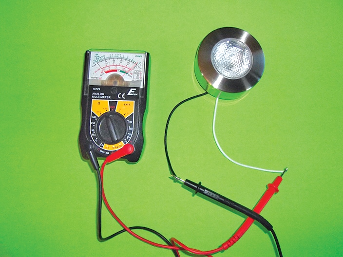
[1] A 10-watt bulb should read about 0.8 ohms resistance.
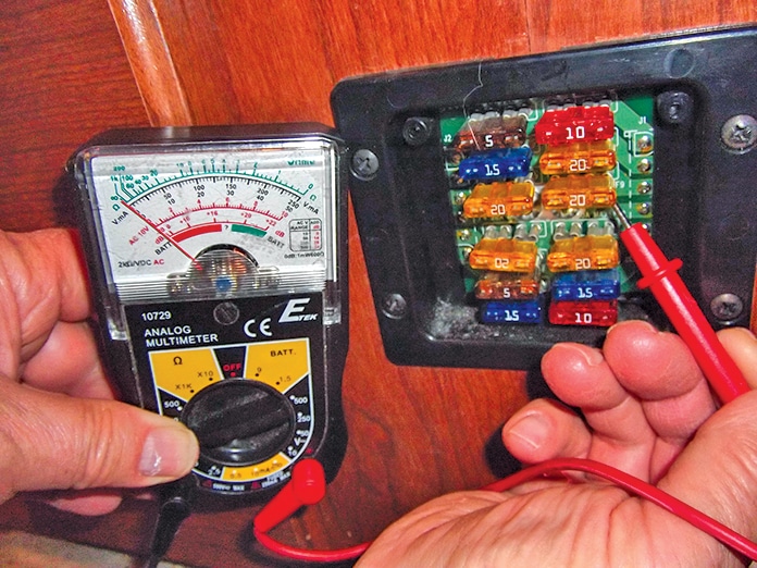
[2] With the negative probe grounded, a fuse should read 12 volts DC on both sides. In this case, the fuse is blown so the meter reads 0 volts on the downstream side.
A motorhome may often have two circuits to control power to one device: one light-duty wire through a switch powering
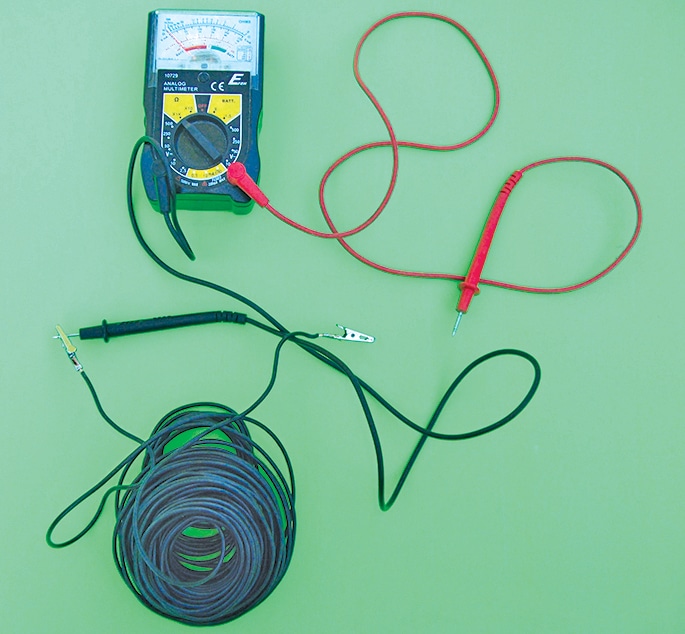
[3] Along with a multimeter, a long wire with alligator clips on both ends is needed for testing ground connections.
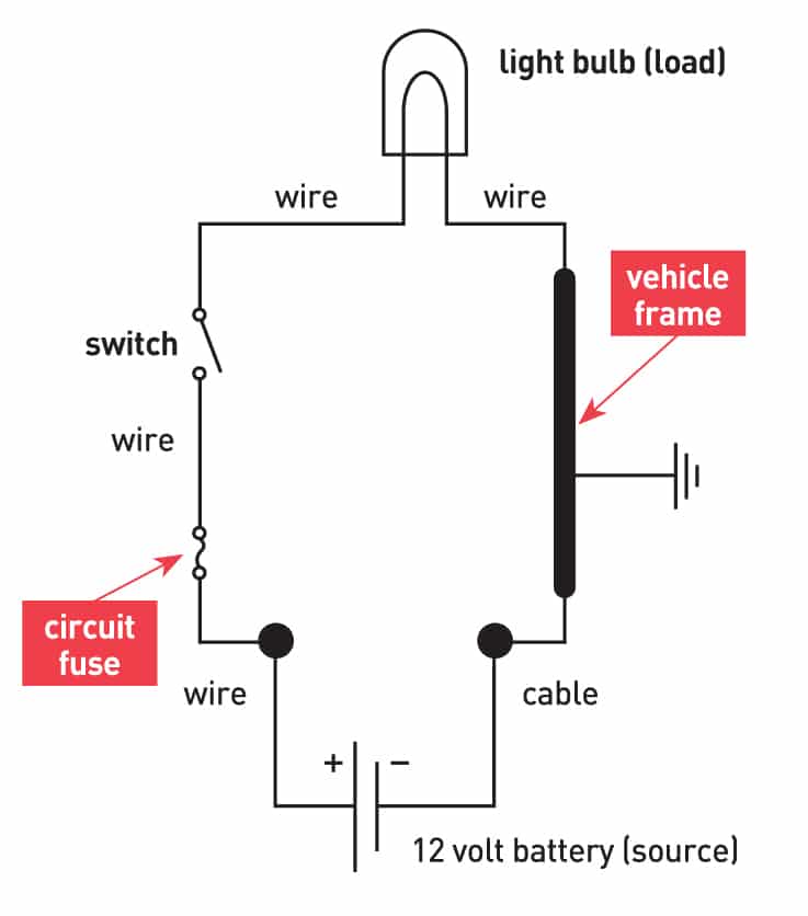
All direct-current circuits are fairly simple and conform to the simple diagram or pattern shown in photo 6. The same steps are followed to troubleshoot any light, device, motor or appliance. To visualize connections to a variety of loads merely substitute the light bulb shown in the diagram with whatever light, appliance, relay, motor or device is failing. The colors used for ground wires in 12-volt DC electrical systems will typically be white, black or green.
Using electron flow notation the actual moving electrons in a DC circuit flow from the negative post (smaller post) of the battery where a surplus of electrons are found along the vehicle frame and then through a ground wire to the load (light bulb, fan, appliance or electric device). Then, they pass through an on/off switch or relay along the positive wire to a fuse on the fuse block, and then to the positive post on the battery where a shortage of electrons exist.
Fortunately both the chassis and the coach DC wiring share a common ground point, the motorhome chassis frame and anything metal physically connected or wired to it. The chassis battery and the coach batteries are both connected to the metal framework.
Troubleshooting for Poor or Lost Grounds
Checking for the most obvious is often overlooked when something fails. Ask these questions as you begin your DC troubleshooting.
-

An example of a simple direct-current circuit.
Has only one light or appliance failed? If not, then the battery cables or battery discharge is the cause.
- Is the device’s switch or main switch turned on? If no, make sure the device is turned on or battery disconnects are set to power on.
- If it is a plug-in device, is it plugged in properly? If no, push in the power (cigarette lighter) plug or check for a built-in fuse that failed.
- Is the fuse OK or is the circuit breaker on? (Not tripped) If no, change the fuse or reset the breaker.
- Do other similar lights or devices that share the same fuse still work? If no, a branch wire, main fuse or fusible link failed.
- Do I know or can I find out where the switches, fuses, relays and wires are located? If no, find a diagram or check where the wires run.
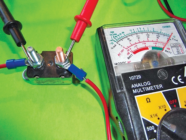
[5] A 12-volt DC circuit breaker should read about 0 ohms.
Use the voltmeter feature to verify that the battery or bank of two 6-volt batteries is charged and tests at 12-plus volts.
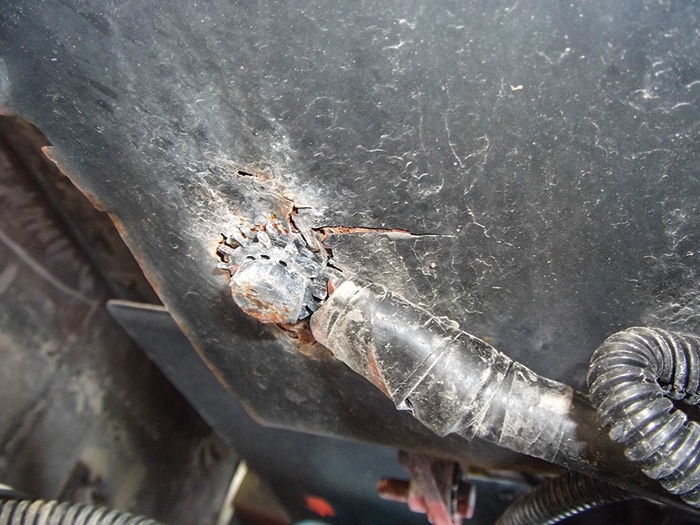
[6] The heavy negative battery cable should be properly grounded to the frame. Oxidized or frayed connections like this one should be repaired even if they test OK to prevent troubles down the road.
Place the alligator clip on the test wire on the negative post and the other clip on the other meter probe, then follow the heavy negative battery cable-to-ground connection on the chassis. (An example of a cable-to-frame connection is shown in photo 5. The second probe is touched on a bare part of the frame to test the resistance from the battery post to the frame. Here, readings should be 1 to 3 ohms because of the cable and test wire resistance. Readings higher than that require attention by cleaning the posts and reconnecting the cable connections.
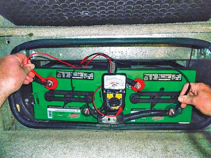
[7] Use the voltmeter function of the multimeter to verify that the battery or bank of two 6-volt batteries (shown) is charged; a fully charged battery will test at 12.7 volts.
The running light bulb is removed from the socket. The red positive test probe is touched to the connection points and
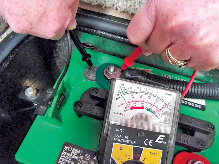
Check the battery negative (—) post-to-cable connection by using the ohmmeter function of the meter, with one lead on the battery post and the other on the cable connector.
a 12-volt DC reading was achieved indicating a ground connection failure for our example. It is quickly verified by connecting one alligator clip to the battery negative post or shiny metal on the frame and touching the base of the light socket with the other clip after reinstalling the light bulb. The bulb should light.
If a 12-volt DC reading was not found at the light socket, the next test would be at the switch. If a 12-volt DC reading is not achieved at the switch (when turned on), move to the next step.
Test the circuit fuse. If you have a 12-volt DC reading on one side and not the other, the fuse has failed. If a 12-volt DC reading is not present on both sides, trace the fuse
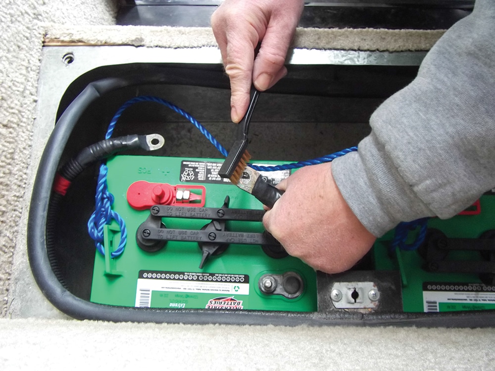
[9] At the beginning of every season, detach the connection cables and clean with a wire brush.
This same set of steps, in order, would be used to test any light or device failure. Once the failure point is discovered make the repair to fix the problem and eliminate the probability of similar failures in the future. Clean and reattach the connections and replace any damaged section of wiring.
Preventive Measures
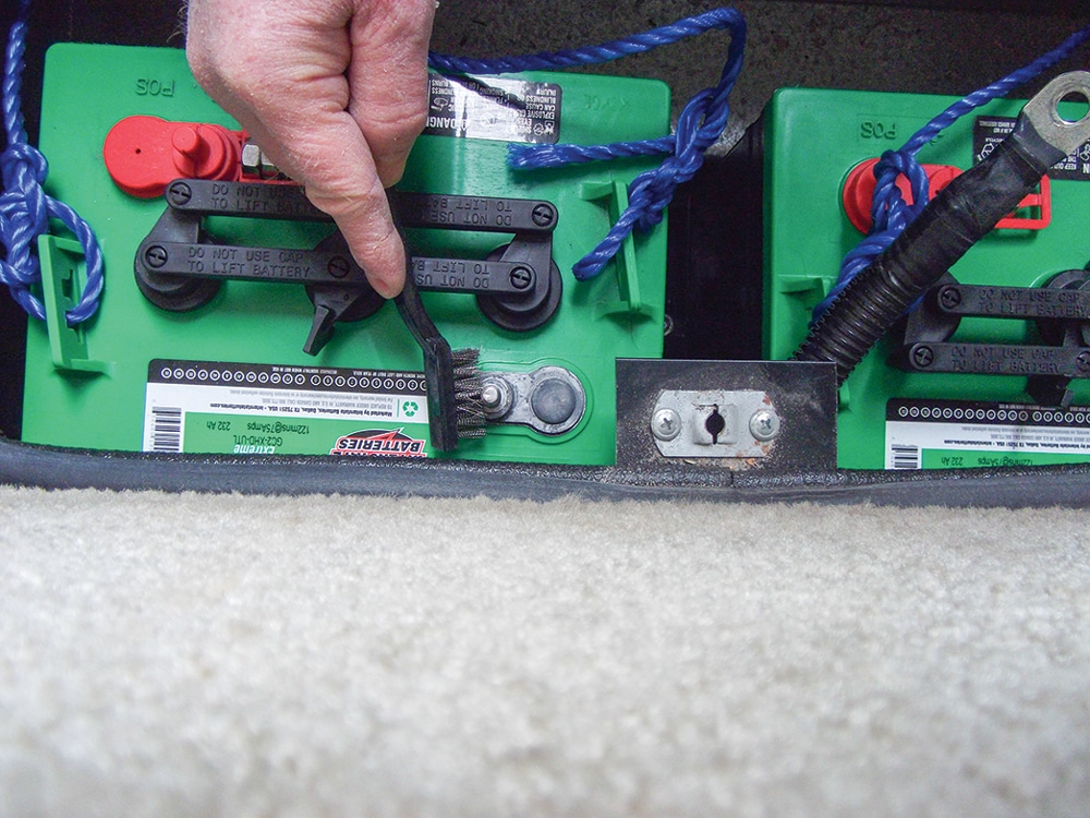
[10] While the cables are disconnected, clean the terminals with a wire brush as well.
- At least annually, clean all connection cables with a wire brush to ensure a firm metal-to-metal mechanical connection at all battery joints as shown in photo 9.
- Clean the battery posts with a wire brush as well as shown in photo 10.
- Use an anti-corrosion pad at all battery cable connection points as shown in photo 11.
- Use an anti-corrosion coating such as the one shown in photo 12. Spray on all exposed battery and ground connections following the instructionson the can and renew the spray every 90 days.
![[11] In addition to preventing corrosion, felt terminal pads like this one are color coded, which makes it easier to discern the positive and negative terminals.](https://www.rv.com/wp-content/uploads/2020/12/figure_07-300x225.jpg)
[11] In addition to preventing corrosion, felt terminal pads like this one are color coded, which makes it easier to discern the positive and negative terminals.
- Should you find yourself cleaning and repairing to-chassis ground connections, use anti-corrosion spray there also, covering an area about 1.5 inches in diameter around the point of connection.
![[11] In addition to preventing corrosion, felt terminal pads like this one are color coded, which makes it easier to discern the positive and negative terminals.](https://www.rv.com/wp-content/uploads/2020/12/figure_07.jpg)
The above maintenance steps will help keep your rig well-grounded, allowing you to enjoy your travels.
Battery Basics
![[12] Once you’ve thoroughly cleaned the terminals and cables, apply a sparing amount of battery terminal protector spray or dielectric grease to prevent oxidation from forming on the bare metal.](https://www.rv.com/wp-content/uploads/2020/12/figure_08.jpg)
[12] Once you’ve thoroughly cleaned the terminals and cables, apply a sparing amount of battery terminal protector spray or dielectric grease to prevent oxidation from forming on the bare metal.