Garnet Instruments Uses External Sensors and High-Grade Electronics to Eliminate Erroneous Readings
Holding tanks make it possible to experience true self-containment in any motorhome, but keeping track of the content level can be frustrating. The vast majority of holding tank gauges leave a lot to be desired. Inaccurate monitoring can usually be traced to probes that are susceptible to corrosion and a build-up of residue caused by poor cleaning habits. These probes are usually screwed into the side of the tank and end up sensing moisture inside the tank walls even after the contents have been emptied. The result leaves owners in the dark when it comes to knowing the true content levels and when it’s time to empty the gray and black tanks. Garnet Technologies takes a different approach to sensor placement and markets the SeeLevel II Tank Monitor System that ties in solid-state electronics and provides accurate measurements without being affected by probe fouling.
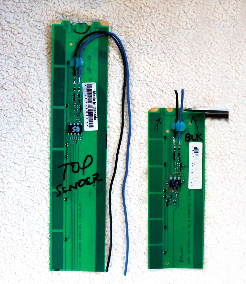
The kit comes with 12-inch senders that are used
on 13-inch or taller tanks. A smaller sender, which
is shown on the right, can be ordered for use on
shallower tanks.
The key to SeeLevel’s accurate monitoring is a specially designed inductive sensing strip that is mounted to the side of any ABS or polyethylene holding tank. Water/waste level is read through the tank wall and processed using patented digital techniques that are pre-programmed into the sender microprocessor. When the sender transmits the water/waste level information to the display, it sends a digital code that has built-in error detection. The sender also transmits diagnostic information about its operation. This information can be used to determine if there is a buildup of sludge on the inside of the tank, or if the sender is delaminating from the side of the tank.
Information from the sender panels is transmitted through a simple two-wire system and is displayed on the monitor in percentage of full in a three digit, LED window. When the selector button for a particular tank is pressed, the display powers up and reads the level for that tank. The display will show the level for about five seconds and then shut down automatically. If another button is pressed before the display shuts down, the level for the respective tank will immediately be shown. If the same button is pressed twice, the display will continue to show updated levels in that particular tank for five minutes – a valuable feature when filling a tank with water for flushing.
The digital nature of the tank level sensing technology and the diagnostic attributes make it almost impossible for the system to indicate an incorrect water/waste level. In the unlikely event an error was to occur, the user can discover the issue using SeeLevel’s diagnostic information.
The toughest part of the installation will be gaining access to the water and gray/black holding tanks. Fortunately, the test motorhome used to install the system allowed easy access to all three tanks.
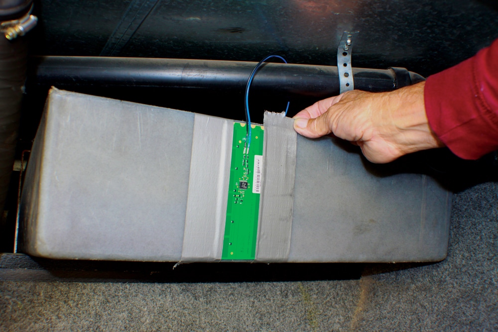
For testing purposes, attach the sender to the desired location
on the tank using duct tape before permanently mounting.
Before starting the installation, it’s best to flush out the gray and black holding tanks thoroughly so that accurate baselines can be determined at the calibration stage of the process. Using a tank-flushing device, like the No Fuss Flush, is the best way to clean out the black tank. Consider attaching a clear fitting between the termination pipe and dump hose so you can monitor when the tanks are clean. And if the tanks have been in service for a while, it might be wise to use a commercial RV tank cleaner to make sure any sludge is removed. In some cases, you might have to let the water and cleaner stand in the tank(s) for a few days so all the soap scum, oils, tissue and waste are broken down. Once this is done, drain the tank(s) completely before proceeding with the installation.
Determining the location for the senders is the most important task before installing the system. The sender will be attached to the side or end of each tank. Most water tanks require the sender to be installed 1 inch above the bottom of the tank because the pump port does not allow for the water to drain completely. When determining a location for the sender mounting location, make sure that there are no metal structures nearby.
Once you are certain the SeeLevel is working properly, remove the duct tape and permanently adhere the sender into position.
Locations for the senders will be influenced when in close proximity of ferrous metal brackets or frame components. Garnet recommends a minimum of 2-inches clearance from any metal that may be lying across the face of the sender board after mounting on the holding tank. Covering the metal with a rubberized material might help if the clearance is compromised. Likewise, Garnet recommends staying well away from large metal components, including metal plates or covers.
If the tanks are exposed to the elements (where there is no belly pan), protection of the sender boards from road spray and debris is necessary. Garnet recommends the use of a body undercoat made of tar-based material, which will cling well to the sender boards and protect them from water and debris. Products like 3M’s Rubberized Undercoat, are available at most auto parts stores. Make sure you do not apply the undercoat until the install is complete and tested for proper operation; removing the undercoat is very tedious and messy.
Some tanks will be difficult to access, which makes it even more important to use duct tape to hold the sender in place to verify operation before permanently mounting.
Once the correct sender is determined for each tank, it will need to be programmed by cutting the appropriate tab at the top of each strip for the respective tank. For example, to make the sender work properly for the gray tank, you’ll simply cut the “GRY” tab at the top of the sender strip; “BLK” will be cut for the black tank. The sender defaults to the freshwater tank, so no cutting is needed when used for this application.
If the tank is taller than 13 inches, two senders will need to be stacked. If this is the case, the tab labeled “TOP” will have to be cut on the sender strip that’s used at the top. For the freshwater tank, there are no cuts made to any of the tabs on the bottom sender. However, the tabs for the respective black and gray tanks will have to be cut on each sender. The unit’s instructions have complete details about this seemingly confusing procedure.
Before mounting the sender permanently, position it against the tank and outline with a felt-tip marker. Use duct tape to hold it in place temporarily, making sure there are no air gaps on the sides of the senders. This will allow for a test run on the system to make sure the chosen locations for the sensors are producing the correct values on the monitor. Most tanks have a smooth surface, however, the use of 220-grit sandpaper will help smooth out any rough areas.
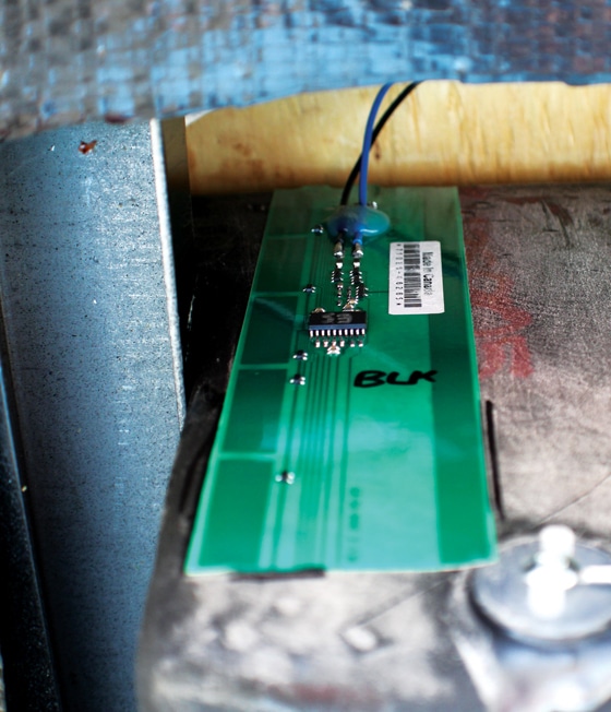
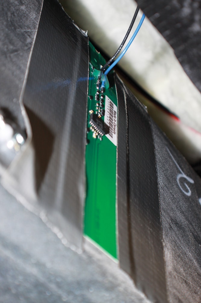
With the sender mounted permanently
to the side of the tank, make sure the blue and black wires do not run across the face of the sender.
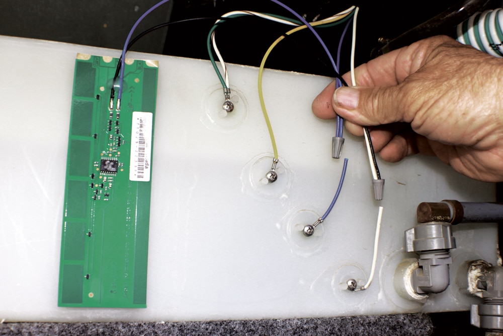
The next step is to wire the system. First, connect all sending unit black wires together and all blue wires together. Find the white wire (the ground wire used in almost all factory monitors) and one other color wire from the existing system (going to old probes) and connect the black wires to the white and the blue wires to the other. Once this is done, make sure the wires are routed away from each sender; secure them with cable ties or cable clamps. This will prevent inductive signal interference and protect the wires from breaking over time.
Next, find a suitable location for the new monitor panel. If the monitor is the same size as your original, it can be installed in that location. If the display is smaller or larger and a new hole is needed, mount the monitor near the original to simplify wire routing. Remove the old monitor to gain access to the wires coming from the holding tanks and find the white and selected color wire that are connected to the new senders. The white wire will be the ground for all senders and is connected to the black wire from the new monitor (and must be on the same ground
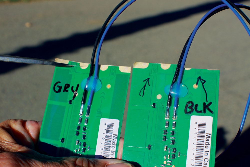
Garnet Technologies makes the senders easy to calibrate by
simply cutting the appropriate tab. Using a black felt pen,
mark the gray and black tank senders before cutting the tabs
to avoid confusion during installation.
plane); the blue (sender information wire) connects to the selected color wire going to the old unit. The SeeLevel display requires 12-volt DC power. The red, 18-gauge wire from the display can be attached to the power source running to the original monitor.
SeeLevel includes a pump switch as part of the monitor; however, the switch is only designed to carry a maximum of 6 amps of current. If you have a high output water pump that draws more than 6 amps, you will need to use the original pump switch in the existing monitor panel. Another option is to install a Bosch-type relay in the circuit, which makes it possible to connect to the pump switch in the SeeLevel monitor.
The monitor display will need to be calibrated using precise, step-by-step instructions that are provided to program the number of senders for each tank. Once completed, fill each tank to about ¼ full and take a reading from the monitor; each tank should display roughly 25 percent. If any error codes are
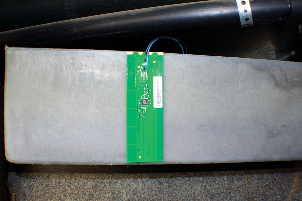
The sender is attached permanently to the water tank and
wired to the blue and white wires that run to the display.
displayed, consult the owner’s manual for specific instructions.
After complete testing and calibration, remove the duct tape, clean the tank location with alcohol or acetone, peel the protective sticker from the 3M tape on the back of the sender and install it inside the outlined location of the appropriate tank; repeat the process for each tank.
The SeeLevel installation can run from easy to difficult, depending on the specific location of the individual tanks and gymnastics needed to gain access to each tank. Water tanks can be hidden behind false walls as well as in the underbelly of the motorhome. Generally, holding tanks are side-by-side, but they may be well hidden. Just be sure to plan for patience and extra time. Since access was easy in the test motorhome, the installation and calibration ran just a little more than two hours.
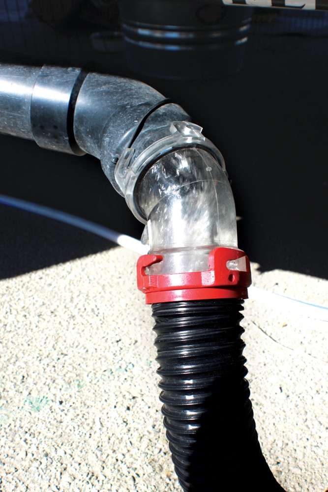
Use a clear elbow at the end of the sewer hose to monitor the cleaning/flushing of the holding tanks. Clean tank side walls will ensure accurate results.
The old adage is true: If it’s worth having, it’s worth working for. Considering the consistent reliability of the SeeLevel and the accuracy in displaying the true levels of each holding and water tank, the installation time and potential difficulty with access is certainly worth the effort. SeeLevel offers different models; the most extensive unit also includes several additional features as well as temperature readings and alarms.
Tested here was the basic SeeLevel II System, Model 709—P3, which retails for $235 and comes with a one-year limited warranty.
Garnet Instruments Ltd. | 877-668-7813 | www.rvgauge.com
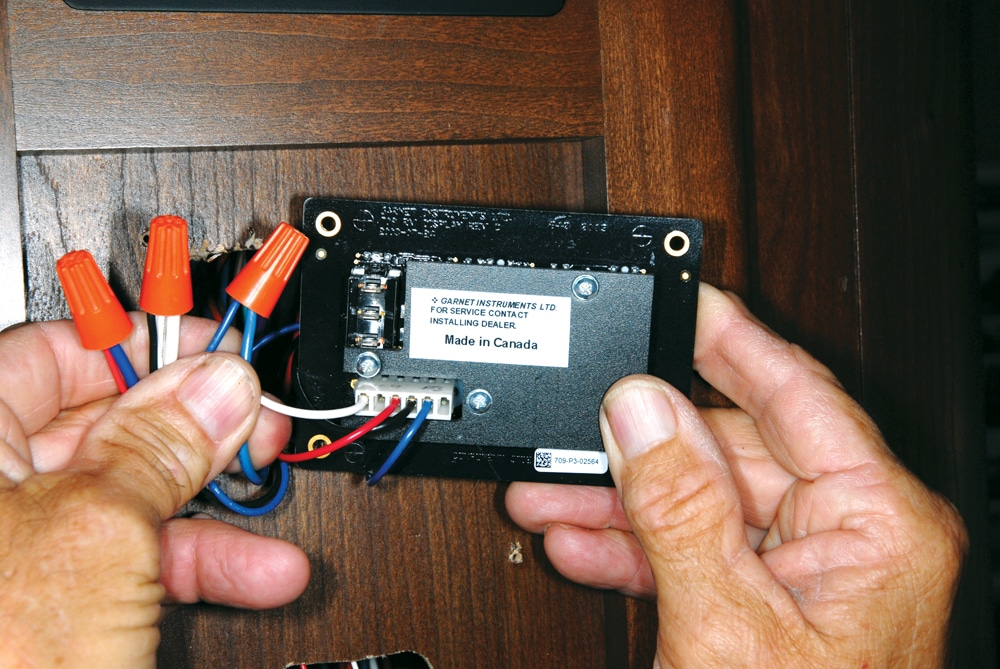
Garnet Technologies has made connecting to the display a simple three-wire hookup. Connecting a positive, negative and sender wire is all that’s required.
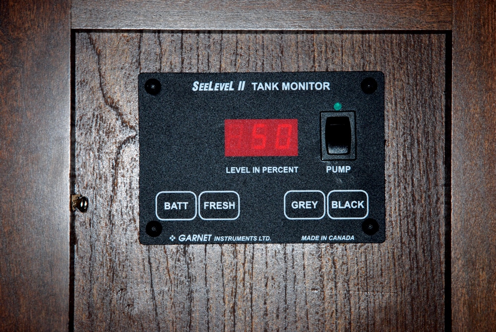
After the SeeLevel system has been installed, add water to either the gray
or black tank and press a button on
the display for the percentage reading.
In this case, the black tank is showing 50 percent full.
 Bill and Jenn Gehr, along with their two Boston bulldogs, are full-time RV adventurers who enjoy sharing their technical knowledge with fellow RVers.