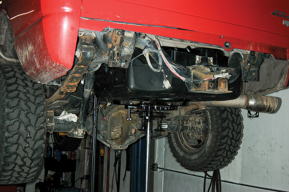
The Titan auxiliary fuel system installs in place of the spare tire and provides 30 gallons of added capacity
Towing a large trailer or fifth-wheel is a lot of fun until you have to stop for fuel. The sheer size of the combo usually makes one have to plan ahead for fuel stops where the facilities can accommodate such vehicles. One way many RVers address this issue is with a large in-bed toolbox/fuel tank or some type of stand-alone refueling tank that extends the period between stops. This is not a bad way to go, but for many, the idea of losing bed space between an auxiliary tank and fifth-wheel hitch, for example, is less than ideal. For these RVers, Titan Fuel Tanks has come up with a variety of molded spare tanks for nearly every popular truck platform on the market today, offering versatile solutions to the bed-space problem.

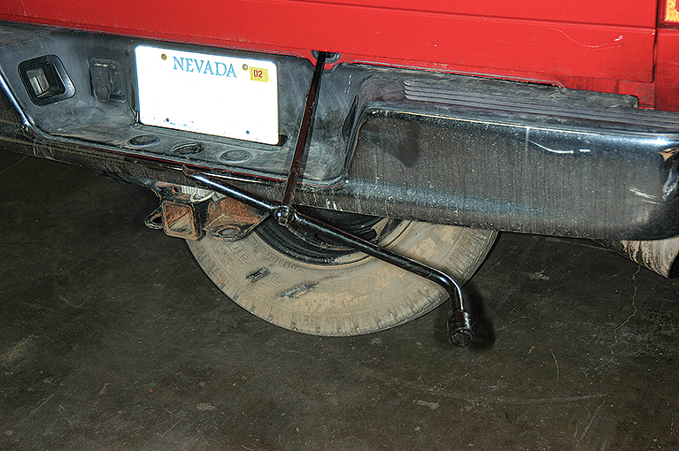
- (1) The install of the Titan STAFS starts by lowering the spare tire from the rear of the truck; the tire will require storing in the truck bed.
One of Titan’s new tanks, quickly gaining the attention of many truck owners, is the Spare Tire Auxiliary Fuel System, or STAFS. STAFS is exactly what the name implies, a 30-gallon auxiliary fuel tank that takes up residence in place of the factory spare tire under the bed. Granted, the installation of STAFS requires that the spare tire be stored and secured in the bed, which will take up some cargo space but still nowhere near as much as a bed-mounted auxiliary tank. Titan’s Spare Tire Buddy offers a simple solution to relocate the spare in the bed of the truck with zero drilling or bolting.
The STAFS is made of injection-molded, military-grade, cross-linked polyethylene using an ultra-high-technology combination of 3D scanning and 3D computer-aided design. Each STAFS tank is model specific to provide the best possible fit. The kit comes with all the correct parts and pieces needed for a complete, professional installation, including the pump, hoses, clamps, extra wiring with terminals, a new fuel filter and detailed instructions, which eliminates those unnecessary trips to the hardware store.

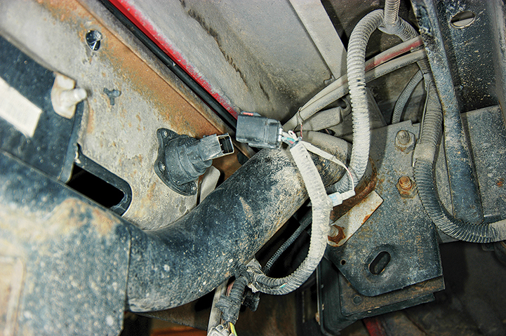
- (2) Before removing the bumper, the license-plate light is unplugged
Let’s take a moment to go over some of the things to consider before taking on this do-it-yourself project. First off, it’s DIY possible but not necessarily an entry-level task. Yes, it can be done in a driveway, but an automotive lift is highly recommended and will simplify things tremendously. With that being said, here’s a small shopping list of what will be needed to best handle the install, especially if the truck is your primary vehicle. One tool that is definitely required, but not included in the kit, is a 43/4-inch bimetal hole saw. This is not an area where saving money makes sense; get a good brand saw, such as those made by

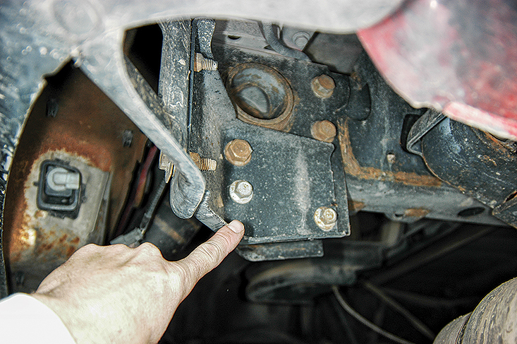
- (3) Bolts are removed from the attachment brackets to release the bumper, which is set aside.
Milwaukee, Starrett or Lenox — available at reputable industrial-supply stores that specialize in saws and blades. Expect to pay around $40 for the hole saw. Another item to seriously consider is 1/4-inch plastic split-loom conduit for any exposed wires; unfortunately, the kit supplies only enough to cover the pigtail coming directly off the electronic controller. And finally, consider using 1/8-inch aluminum plate to fabricate a basic splash guard to protect the new pump and filter from potential gunk buildup from the tires. We’ll be installing one in the near future. A helper is also a good idea.
Once everything is gathered, installation of the STAFS

- (4) Once the bumper is out of the way, it’s easy to remove the spare-tire winch assembly.
starts by lowering the spare tire from under the bed. The tank was installed in a Ram 2500 four-wheel-drive with larger-than-stock tires, so the smaller spare was not useful to us, and losing it was not an issue. Before the truck is raised, take a few minutes to remove the bumper, which gains a lot of working space for this project. Make sure to look behind the license plate for hidden bumper bolts. With the bumper unbolted and placed aside, the spare tire and its entire winch assembly can be removed. From here, some minor assembly of the truck-mounting plate must be performed using two of the large 3/4-inch serrated flange nuts and the precut 3/4-inch threaded rod included in the kit. It’s important to make certain that at least two threads are showing once the nuts are properly torqued.
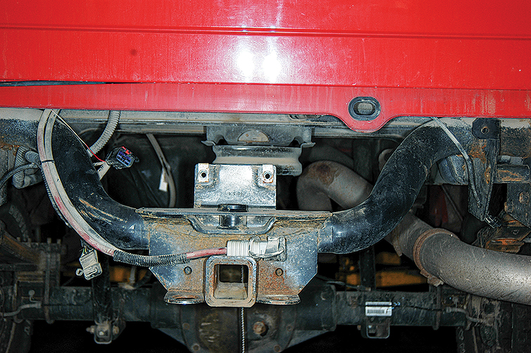
Now the truck-mounting plate is ready to bolt to the old spare-tire winch location with the provided two 8mm bolts, nuts and washers.

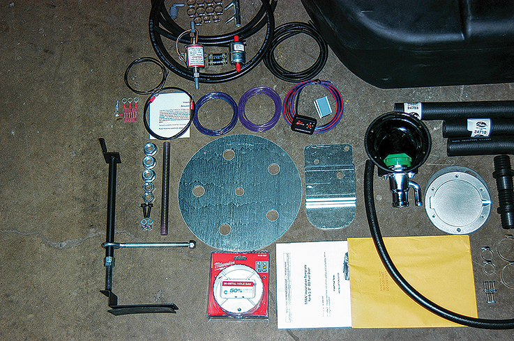
- (5) The Titan STAFS kit comes with all the necessary hardware for installation.
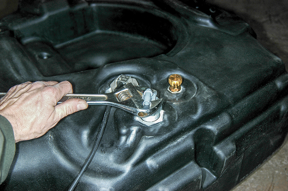
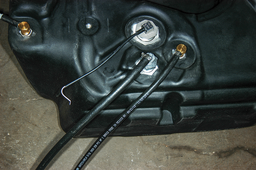
The tank must then be prepped for placement and the 5/16-inch and 3/8-inch hose plumbing affixed to the top part of the tank. The locations for the fittings and hoses will be obvious; we simply angled the fitting in the same direction for a good fit. The grounding wire is connected with a small machine screw, and the fuel sensor leads are spliced with the supplied heat-shrink terminals.
Now the tank can be test-fit for the first time, marking the filler- and vent-hose pathway and routing for the pump, filter and hoses. This is best

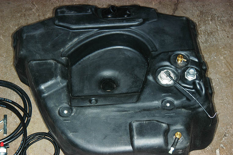
- (6) The tank is precisely molded to fit in the area once occupied by the spare tire.
accomplished by lifting the tank into place with the tank-mounting plate located beneath, assuring the alignment of the bottom circular mounting tabs. At this point, the flange nut is tightened just enough to hold the tank up. Take a close look at anything that may obstruct the filler- and vent-hose path and either bend or remove any material in the way. Be absolutely positive there are no sharp edges that could contact or rub any hoses or wiring; if so, take care of it now. You’ll notice when routing and measuring for the filler and vent path, there’s quite a bit of excess hose length, so feel free to trim a little at a time, as needed.

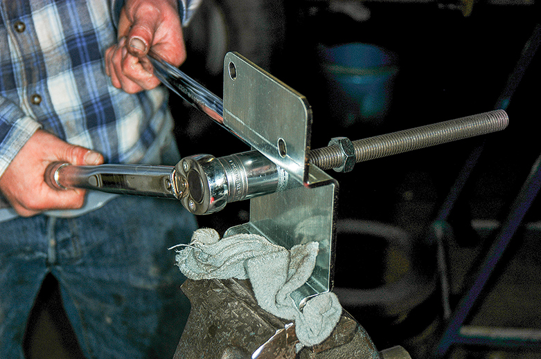
- (7) Minor assembly of the truck-mounting plate is accomplished using two of the large flange nuts and the presized ¾-inch threaded rod.
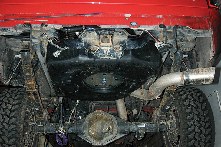
Once all the final fitting and trimming have been completed, the tank can be permanently mounted by tightening the 3/4-inch flange nut to 15 ft-lbs and the thin locknut to 45 ft-lbs. It took about four or five trips up and down with the tank before we got the final plumbing routes and metal trimmed correctly; it simply requires patience and time.
Although not necessarily sticking to the directions, we found it best to complete all of the hardware placement, such as securing the filler neck, filler door, pump, filter and all hose routing, before tackling any wiring. So we skipped around a bit and just left the wiring as its own separate task. Doing so also allows for all hose and wire routing to be true and not require secondary work.
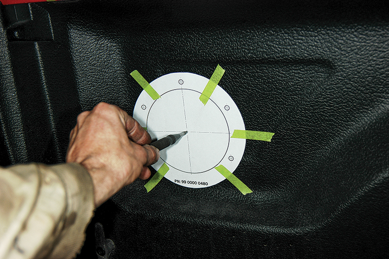
At this point, a decision has to be made where to locate the filler door — inside or outside the fender. For us, the idea of cutting a hole in the exterior of a $50,000-plus truck was bothersome, so inside the bed it went. Take your time — you don’t want to make a mistake with a 43/4-inch hole saw! Map it out, mark it carefully with the provided template and cut with confidence. If going through a bed liner, the screw length may need to be compensated for, as was the case with the project truck. After getting the new fuel-filler neck and door in place, the only remaining hardware to focus on was the pump and filter assembly, as well as final hose routing and tightening of clamps.
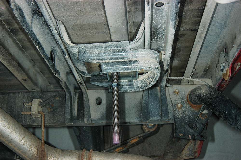
- (8) The truck-mounting plate is bolted to the old spare-tire winch location using supplied fasteners.
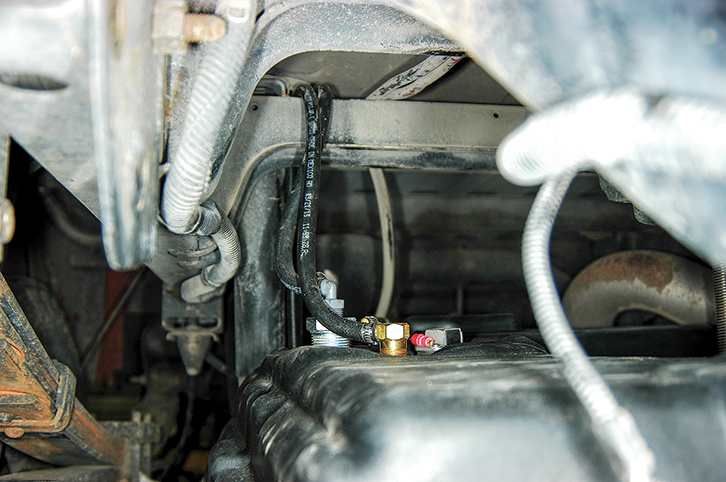
While trying to pinpoint a new home for the pump and filter, aim to keep them out of the way of excess water or debris but still allow for the hoses to reach with ease and remain kink-free. In the midst of running and routing hoses, the factory tank vent line must be cut and the vent-fill neck adapter spliced in. This is the point where fuel will be pumped in from the Titan tank. Be sure to double-check which adapter in your kit is the right one before cutting the vent line. There were two vent-line sizes in our truck, and, as it turned out, we needed to use the larger of the two vent-fill neck adapters.
- (9) The Titan tank is prepped on the bench by adding the hose fittings; location is obvious, and the fittings are simply angled in the direction necessary for best hose routing.
After determining the best spot for the pump and filter to reside, it can be fastened with self-tapping screws, and all the corresponding hoses can be routed to and from the vent-fill neck adapter, pump and STAFS tank. Follow instructions carefully here and be aware that you’re working in the presence of gasoline vapors, so eliminate any potential ignition sources before beginning this part of the job.
The remaining portion of the project involves wiring the fuel sensor, pump and electronic controller together. We simply tackled the wiring beginning with the tail end of the truck and working forward, which left two grounds and a purple wire extension that were added earlier. To save some time and effort for the ground wires, an existing bolt in the frame was removed and replaced with the two terminals sandwiched in between. Make sure the surface has exposed metal for any grounds. The aforementioned purple wire is easily run along the same route as the pump hoses, where it can be joined with the pump and electronic controller. From this point, the blue wire extension from the pump is connected to the purple wire extension and fed together along the frame, up to the driver’s side of the engine compartment, to the fuse box. This is a good example of where to use the 1/4-inch plastic split conduit mentioned earlier in our shopping list.
- (10) Hoses are connected to the fittings before mounting to the tank.
The last step is to find a suitable mounting location in the cab for the electronic controller. The pigtail is long enough to allow for mounting versatility. It was routed through the firewall and connected to the fuse box using the fuse tap and spade connector. A nearby factory ground location was used for the negative wire. Once the install is complete, the tank must be filled to capacity, or the warranty will be voided.
The STAFS tank, at first, seems cumbersome and quite difficult to deal with on the install side of things, but Titan engineered a precise fit and provides excellent instructions, so much of the anxiety is lost. However, you’ll probably spend the better part of a weekend on this job. The tank kit retails for $1,768 plus shipping.
(11) The fuel-sensor wire is attached and ground lead is secured using a small machine screw. |
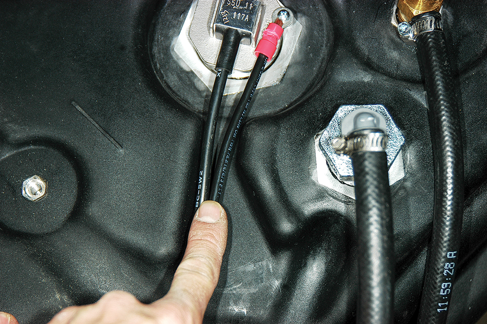 |
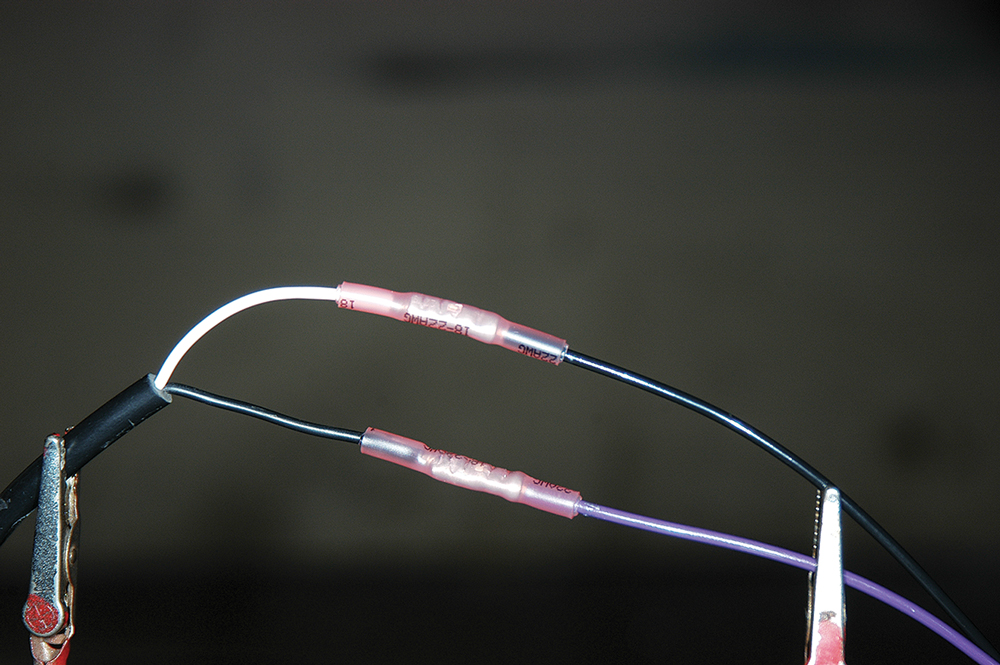
(12) The fuel sensor and ground leads are spliced into the wire loom using butt connectors with shrink tubing. |
 |
(13) The new tank is test-fitted using an equipment hoist. Having a vehicle lift available makes installation much easier. |
 |
(14) The hoses are carefully routed before mounting the new tank. |
 |
(15) The hose must have a clear path without kinking and be far enough away from anything with sharp edges. The kit’s hoses are longer than necessary, so routing and trimming allows for a good fit. |
 |
(16) After the final fitting, the tank is permanently mounted by tightening the flange nuts. |
 |
(17) A template is used to cut a hole for the filler door. |
 |
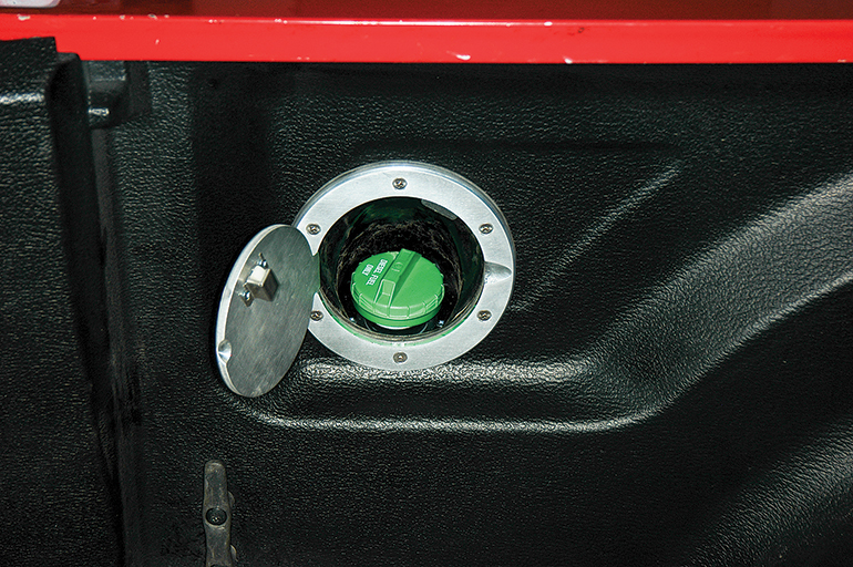
(18) The decision was made to locate the filler door inside the bed rather than make a hole in the exterior sheet metal. Access is a little more difficult, but the filler door does not detract from the outside aesthetics of the truck. |
 |
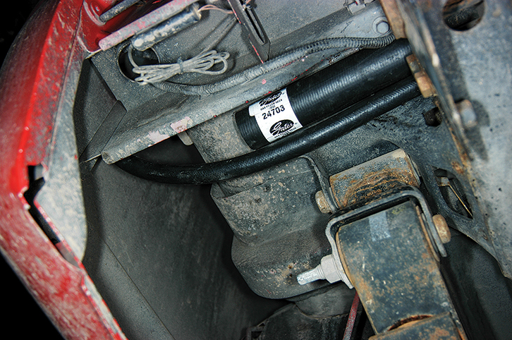
(19) An independent pump is used to transfer fuel to the main tank. |
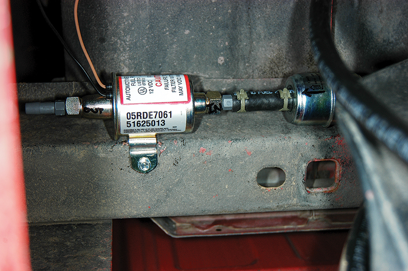 |
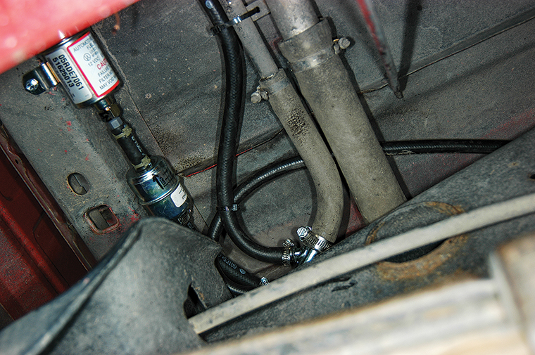
(20) The STAFS pump and filter are neatly tucked up out of the way and secured to a frame member. |
 |
(21) An electronic controller can be mounted on or under the dash, or any other convenient location for monitoring. |
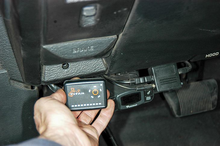 |
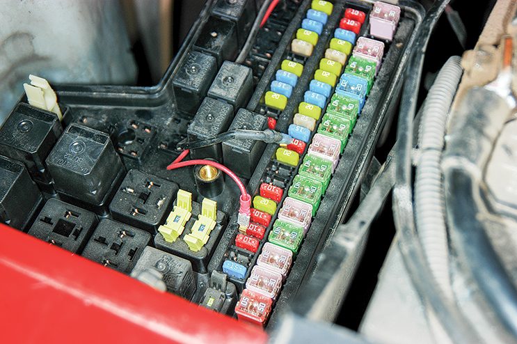
(22) Power is tapped from the fuse compartment located under the hood of the truck. The fuse tap makes connection simple. |
 |
Titan Fuel Tanks | 800-728-4982 | www.titanfueltanks.com